SSSICK/Installation: Difference between revisions
< SSSICK
m (Sssquid moved page Main Page/Installation to SSSMCK/Installation) |
No edit summary |
||
| Line 10: | Line 10: | ||
==Hardware== | ==Hardware== | ||
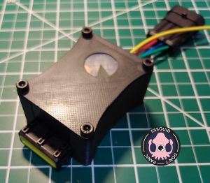
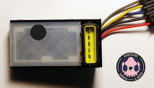
Determining which version of the kit you have is necessary before following wiring guides or otherwise. There are 11 total released versions. The 3 most recent and common versions are: R017, R018, and R019. | |||
[[File:SSSMCK_R017.png|center|thumb|R017]] [[File:SSSMCK_R018.png|center|thumb|R018]] [[File:SSSMCK_R019.png|center|thumb|R019]] | |||
=Installation= | =Installation= | ||
Revision as of 19:49, 25 June 2022
Prerequisites
Tools
- Flat-head screwdriver
- Any other applicable tools to remove and install your particular intake system
- Soldering iron (may be necessary)
- Wire stripper (may be necessary)
- Terminal crimper (may be necessary)
A few tools are marked as "may be necessary". This depends on if you are wiring your own pigtail or if you are wiring power in a specific way. Many people will require nothing more than a flat-head screwdriver and the other tools necessary to remove the original VAM (usually a 10mm socket and flat-head is all that's needed).
Hardware
Determining which version of the kit you have is necessary before following wiring guides or otherwise. There are 11 total released versions. The 3 most recent and common versions are: R017, R018, and R019.
Installation
- Remove the 10mm bolts holding the intake filter box in-place (there will be 2-4 depending on model, engine, and production date).
- Loosen the VAM-to-intake elbow hose clamp. Disconnect the VAM from the chassis harness. Remove the VAM and filter box.
- Install your selected MAF in place of the original VAM. You may need to use adapters or a different intake boot depending on the MAF diameter.
- Install your new filter-side intake components.
- Find the VAM harness connection. Pull back the rubber weather protection to expose the harness connection and wires. Feed the supplied 12v supply wire through the large opening toward the small opening. It may help to use a screwdriver or wire-feeder to help the wire through the tighter end of the rubber protector (see fig. 1).
- The terminal will simply snap right into the 5th, empty slot of the stock VAM adapter. The stock VAM does not make a connection with this, so you can switch back to the stock VAM if necessary without any modification to your wiring.
Figure 2
- Run the new power supply wire either to a switched battery source, or replace a fuse with the vampire fuse adapter (the top slot is the fuse for the wire, while the bottom slot is for the original fuse). Make sure the fuse direction is correct! (see fig. 2, 3, & 4)
Figure 4. An example of an installed vampire fuse adapter.
- If not pre-wired, you may need to splice a MAF pigtail to the included universal 5-pin connector. See the below table for a pinout:
| Color | Function |
|---|---|
| RED | 12V |
| BLACK | GROUND |
| GREY | 5V |
| BLUE | MAF SIGNAL |
| YELLOW | TEMPERATURE SENSOR |
- Configuring IAT sensor (optional).
- Not all MAFs contain IAT sensors, please consult your specific MAF specifications.
- Not all IAT sensors operate with the same specifications as is expected by the stock ECU. Check first, Otherwise be either tuned for the specific IAT sensor you will use, or use the internal temp sensor of the SSSMCK.
- If you are using an external IAT sensor, connect the yellow wire to the signal of the IAT sensor, and the other wire of the IAT sensor to ground. Use ONLY 2-wire IAT sensors! GM 2-wire is not exact and will require a specific tune.
- If there is any doubt, it’s best practice to use the built-in temp sensor within the SSSMCK. You can choose between internal and external temp sensors using the jumper as outlined in figure 5. “INT” for internal sensor, “EXT” for external sensor.
- The SSSMCK installation is now complete! You will now install your intake filter setup, following its specific instructions. There are many options to choose from, but we do recommend using a cold-air intake system.
- (Optional, but recommended): If you have a wideband EGO (O2) sensor with gauge, fine sensor adjustments can be made. Disconnect any ECU EGO feedback and perform an ECU reset. Start your vehicle and allow it to reach normal operating temperature.


