SSSICK/BUOY/Tuning
Tuning
Tuning from within Buoy is now available with the latest 0.20.xxxx software! Download it HERE
The defaults may change depending on firmware version, and not all features are available depending on firmware version loaded.
Parameters
Sensors

Input Sensor
There are many different input sensors to choose from: Mass AirFlow (MAF) sensors, Throttle Position Sensors (TPS), and Manifold Air Pressure (MAP) sensors. While each unit is shipped pre-programmed for the sensor you chose at checkout, you can always reprogram it for a new sensor later.
You can use one of the available MAF sensors freely without the need for a specific ECU tune. However some sensors, such as TPS and MAP, require you to have a specific ECU tune in order to run properly.
Output Sensor
This is the sensor that your ECU is tuned for. This is almost certainly the stock VAM that your vehicle was equipped with, unless it was changed and your ECU was retuned for another sensor at some point.
Averaging

Enable to allow the SSSMCK to perform software averaging of signal processing. This is enabled by default.
We recommend a setting of somewhere between 20 and 40. A larger value means slower reaction, but perhaps smoother operation. A smaller value means sharper response, but an overly small value will provide the ECU with too much noise and may cause rocky operation.
- Recommended values based on input sensor used:
- MAF: 10-20
- TPS: 5-20
- MAP: 25-50
What is averaging?
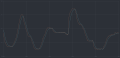
Averaging smooths a signal to allow for better, less choppy reading of a signal. This should offer better operation when tuned correctly. You can see how a raw signal (orange line) is filtered and output (blue line):

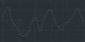
You can see how various averaging values affect the signal below:
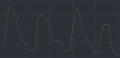
Value of 10
Value of 20
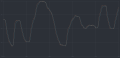
Value of 30
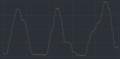
Value of 40
Value of 50
Value of 60
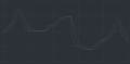
Value of 100


Manual Correction
Enable this to allow the making of manual corrections to output. This scalar is part of a final output equation. Adjusting this directly affects the calculated airflow. (E.G. 100 kg/hr will be converted to 105 kg/hr with a correction scalar of 1.05)
FW 0.20+

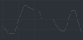
Beginning with FW 0.20, the manual correction is now a linear 2D map that allows you to set linear extrapolated correction based on airflow (manifold pressure for MAP; throttle position for TPS).
The first value is applied statically at all airflow values below, and the last values is applied statically at all airflow values above. Below is an example of how this correction is applied:

Both the scalars and the airflow axis are fully tunable.
FW 0.16-0.19

For FW versions 0.16 through 0.19 the manual scalar was static. This means that the values is applied as a constant scalar throughout all airflow ratings.
Dynamic Correction

Leave this disabled unless you are having issues with fuel ratios that cannot be fixed with minor manual corrections.
This scalar directly affects output signal directly and not airflow values.
Enable this to allow the SSSMCK to automatically make corrections to output based on discrepancies. This scalar cannot be set manually as it is dynamic and the SSSMCK will automatically learn different values for different airflow ranges. The SSSMCK not only outputs a signal, it also reads that output signal to verify that the board is outputting the correct signal. If there is issue with this signal and the "Error Checking" option is active, the SSSMCK will throw an error code. You can enable dynamic correction to correct for these types of issues.
- Correction Limits
- The MINIMUM and MAXIMUM scalar values for how far the SSSMCK can go to make automatic adjustments.
- These settings are limited to no less than 0.90 and no more than 1.10 respectively.
Custom LED Color

With our newer firmwares the LED operation has changed. You can now set your own custom LED color for normal operation. The default normal operation LED color is green. Resetting the unit to default values will also reset your custom LED color to green.
Click the large colored box to bring up a color selection window.
Timer Periods

Adjust these to change how often the SSSMCK will perform certain functions and checks.
Timer Period 1
How often custom trigger and idle checks are performed.
Typical values are 80-100.
Timer Period 2
How often internal checking is performed and dynamic correction is updated.
Typical values are 180-220.
IAT Scaling

Beginning with hardware R020 you can manually tune the IAT sensor output so that non-stock sensors can be used. The values for the most common IAT sensor setups are: Low = 10, High = 1020.
TPS

When using a TPS you must first calibrate the closed and open values. With the engine off and the unit powered, click on "Calibrate TPS" to start the process. With the throttle fully closed, click "Set Closed Value". Then depress the throttle pedal fully and click "Set Open Value". Once you do this, click "Save" to save the settings. The settings will not be applied until you write the settings to the SSSMCK (by clicking "Write").
M40/2 Mode

If you are running M42-compatible firmware, you will be presented with the M42 Mode table. M42's have a little extra wiring involved -- a full tutorial will be available shortly!
The M40/2 VAM has three outputs, one for IAT and two for airflow. Therefore an additional wire is added to units destined for an M40 or M42 engine. M42 mode enables the output of all three of these signals to the ECU.
- Operation Mode
- Default: The standard operation mode, what most people will use.
- Sweep: Used if the "default" option is providing inconsistent results.
- Inverse: We've found that the E36 M42 models prefer this setting.
- Threshold kg/hr
- The airflow rate at which M42 mode is active. Typically this is between 10 and 70.
- Output rate
- A scalar for the additional output signal. This is used to adjust for any possible discrepancies.
Custom Triggers

Beginning with hardware version R020 and newer, there are now 2 programmable triggers that can be wired to a relay to trigger a device (such as NOx, sprayers, etc). You will need to use the appropriate adapter kit to take advantage of these triggers. An example of how you can wire these triggers can be seen in the below diagram:

Enabled User Variables
Starting with Buoy version 0.19.1795 the Enabled User Variable section is automatically calculated and you will no longer have to worry about this option. We recommend using the latest Buoy version. If you need to use older versions for one reason or another, please email us for information regarding this section!
Reset to default values
If you ever have trouble, you can easily reset everything to default values from within Buoy. Simply click the "Reset" button!