Jetronic and SSSICK/BUOY: Difference between pages
| Line 1: | Line 1: | ||
=Introduction= | |||
Buoy is an all-in-one data-logging and tuning tool for the SSSMCK (SSSQUID MAF CONVERSION KIT). It is in beta stages and as such may have bugs. Please [https://sssquid.com/v3/contact contact us] with any bugs you may encounter. | |||
This tool was developed in and for Linux first. The Windows port is in very early stages and will naturally have more bugs than the Linux flavor. There is no version for Mac OSX and we do not have any plans to ever release a version for that OS. | |||
Expect new software to be released regularly. We have not implemented any auto-update functions yet. Please bookmark this page to get quick access to the latest software. | |||
=Download= | |||
Latest Version: 0.18.07 | |||
*Windows | |||
**32-bit (JRE required) - [https://sssquid.com/strg/sssmck/buoy/buoy-001807-win32.zip Download] | |||
**64-bit (recommended for most users! Pre-compiled JRE included) - [https://sssquid.com/strg/sssmck/buoy/buoy-001807-win64.zip Download] | |||
*Linux | |||
**32-bit - [https://sssquid.com/strg/sssmck/buoy/buoy-001807-lin32.tar Download] | |||
**64-bit - [https://sssquid.com/strg/sssmck/buoy/buoy-001807-lin64.tar Download] | |||
**arm32 - coming soon, please contact for early access | |||
**arm64 - coming soon, please contact for early access | |||
Previous versions available by request, though you should most likely be using the latest version! | |||
[[SSSMCK/BUOY/Version_History|Version History]] | |||
==Installation== | |||
This program is designed to be portable -- there is no installation necessary. Simply extract the compressed folder contents to its own directory and run "Buoy.sh" (Linux) or "Buoy.exe" (Windows). | |||
For the 32-bit Windows version of Buoy, the necessary JRE (Java Runtime Environment) is not pre-packaged. You may need to install the JRE if you haven't already: [https://docs.oracle.com/goldengate/1212/gg-winux/GDRAD/java.htm Java JRE]. The JRE is pre-packaged on the 64-bit version (what most everyone will be using). Unless you are running an older 32-bit version of Windows (like 32-bit XP), it is recommended to use the 64-bit version. | |||
For Linux users, Java is required to run but is not prepackaged. Many flavors of Linux will come with the necessary runtime environments pre-installed, but if you're not sure you can check with your package manager. | |||
==Drivers== | |||
Most flavors of Linux will come pre-installed with the necessary drivers. | |||
For Windows, you may need to install the standard FTDI D2XX drivers available at the following link: [https://ftdichip.com/drivers/d2xx-drivers/ FTDI D2XX Download Page] | |||
=Interface= | |||
*Main | |||
**Setup port, flash firmware, and view diagnostic information. | |||
*Live Dash | |||
**View and log live airflow data. | |||
*Log Replay | |||
**View previously recorded logs with many ways to manipulate and filter the data. | |||
== | =Usage= | ||
== | ==Connecting== | ||
With the top cover removed, you will need to find a 6-pin header. This is where the logging/flashing module will be plugged. | |||
[[File:Loggingmoduleport.jpg|center|thumbnail]] | |||
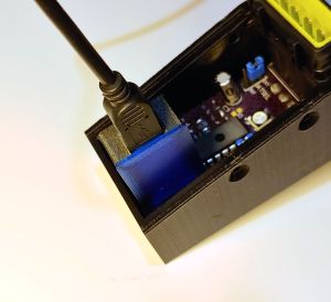
Plug in your logging/flashing module. It can only be inserted in one direction. | |||
[[File:Loggingmoduleconnected.jpg|center|thumbnail]] | |||
Connect the USB cable to your computer. If you are logging, please skip the next step. | |||
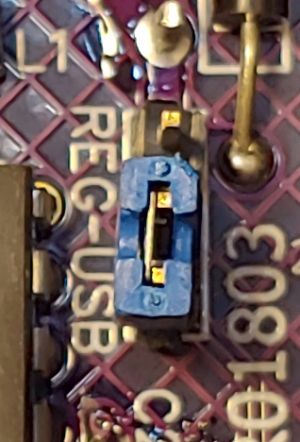
ONLY if you are flashing the module!: it is recommended to use the USB power. You can do this by moving the "REG-USB" jumper from the "REG" side to the "USB" side as pictured below: | |||
== | [[File:Usbpowerselected.jpg|center|thumbnail]] | ||
Once you finish flashing, please make sure to move this jumper back to the "REG" side before continuing use on your vehicle. | |||
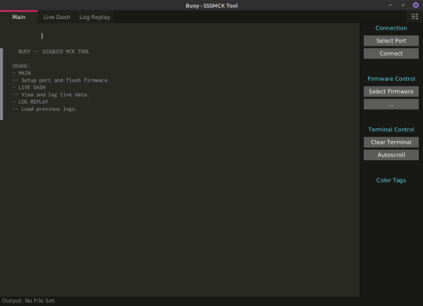
On the "Main" tab you will find the connection and flashing options. | |||
[[File:Buoy001804_main.png|center|thumbnail|600px]] | |||
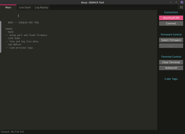
First you will need to select the correct port. Click on "Select Port" and you will be presented with a list of available ports. | |||
If you are unsure of which port the SSSMCK is connected through, you can simply disconnect the device and reconnect it to see which port is added and removed. The list automatically updates. | |||
[[File:Buoy001804_portselected.png|center|thumbnail|600px]] | |||
Once the port is selected, click "Connect". It will take 2 seconds to connect, do not repeatedly click the "Connect" button during this time period. The SSSMCK should connect and automatically start sending airflow data. If data is not graphed on the "Live Dash" page, you can try disconnecting and reconnecting. | |||
==Data-logging== | |||
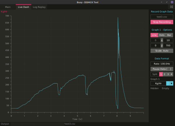
Once connected the SSSMCK should automatically begin transmitting airflow data to the program. This is displayed in kilograms per hour (Kg/Hr). | |||
[[File:BUOY001804_LIVEGRAPH.png|thumbnail|center|600px]] | |||
On this page you can set an output file. Use the file extension ".csv" for logs (this file extension should automatically be added, but there is a bug in Windows where if your file path has one or more periods it may not be automatically added). | |||
Once you have set the output file, you may begin logging by selecting "Start Recording". Once you are finished recording, select "Stop Recording" or simply close the program. | |||
There are many ways to display the data, as a line (recommended and default), as dots, or as bars. The rest of the options are primarily for further diagnostics when necessary, but should not be needed or used by most users. | |||
===Log Replay=== | |||
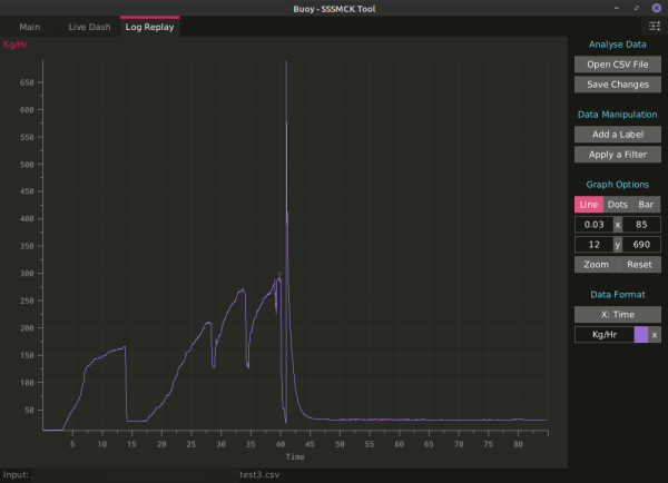
If you would like to view previously recorded logs, you can open them a number of ways. They are output as simple CSV files (Comma Separated Values). These can be read by programs such as OpenOffice/LibreOffice Calc, Microsoft Excel, or within Buoy. | |||
To open a previously recorded log, select "Open CSV File" and browse to the folder where the log was recorded. Select and open the log to populate the graph. | |||
[[File:BUOY001804_LOGREPLAY.png|thumbnail|center|600px]] | |||
You can manipulate the data, apply filters, change how it is displayed, and more by using the "Graph Options" and "Data Manipulation" sections. | |||
==Flashing== | |||
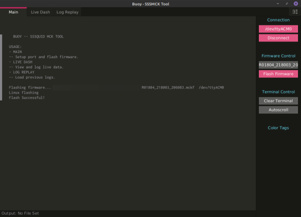
On the "Main" page, make sure you have the proper port selected and are connected to the SSSMCK. Under "Firmware Control" click on "Select Firmware" to be presented with a file explorer. Navigate to the firmware (file extension ".mckf") you wish to flash to the device and select it. | |||
[[File:R001804_flashing.png|center|thumbnail|600px]] | |||
Once you have chosen the firmware, the button underneath it will change to "Flash Firmware". Click this button to flash the firmware. A success or failure message will be displayed in the console log. | |||
==Configuration== | |||
You can configure most of the program's settings, such as the theme and interface scaling, by clicking on the settings icon in the upper-right side of the application. | |||
=Firmware= | |||
".MCKF" files contain the calibrations for the MAF and VAM selected. Since we are constantly releasing new versions, please [https://sssquid.com/v3/contact contact us] with your required MAF and VAM combination and your hardware version, we will reply with a download of the latest available software. | |||
All units ship with the proper and latest available firmware for your selected MAF and VAM, so there is no need to flash a new unit unless you are changing vehicles/tunes/MAFs, there are fixes, or the latest software requires it. | |||
Revision as of 18:38, 18 October 2021
Introduction
Buoy is an all-in-one data-logging and tuning tool for the SSSMCK (SSSQUID MAF CONVERSION KIT). It is in beta stages and as such may have bugs. Please contact us with any bugs you may encounter.
This tool was developed in and for Linux first. The Windows port is in very early stages and will naturally have more bugs than the Linux flavor. There is no version for Mac OSX and we do not have any plans to ever release a version for that OS.
Expect new software to be released regularly. We have not implemented any auto-update functions yet. Please bookmark this page to get quick access to the latest software.
Download
Latest Version: 0.18.07
- Windows
- Linux
Previous versions available by request, though you should most likely be using the latest version!
Installation
This program is designed to be portable -- there is no installation necessary. Simply extract the compressed folder contents to its own directory and run "Buoy.sh" (Linux) or "Buoy.exe" (Windows).
For the 32-bit Windows version of Buoy, the necessary JRE (Java Runtime Environment) is not pre-packaged. You may need to install the JRE if you haven't already: Java JRE. The JRE is pre-packaged on the 64-bit version (what most everyone will be using). Unless you are running an older 32-bit version of Windows (like 32-bit XP), it is recommended to use the 64-bit version.
For Linux users, Java is required to run but is not prepackaged. Many flavors of Linux will come with the necessary runtime environments pre-installed, but if you're not sure you can check with your package manager.
Drivers
Most flavors of Linux will come pre-installed with the necessary drivers.
For Windows, you may need to install the standard FTDI D2XX drivers available at the following link: FTDI D2XX Download Page
Interface
- Main
- Setup port, flash firmware, and view diagnostic information.
- Live Dash
- View and log live airflow data.
- Log Replay
- View previously recorded logs with many ways to manipulate and filter the data.
Usage
Connecting
With the top cover removed, you will need to find a 6-pin header. This is where the logging/flashing module will be plugged.
Plug in your logging/flashing module. It can only be inserted in one direction.
Connect the USB cable to your computer. If you are logging, please skip the next step.
ONLY if you are flashing the module!: it is recommended to use the USB power. You can do this by moving the "REG-USB" jumper from the "REG" side to the "USB" side as pictured below:
Once you finish flashing, please make sure to move this jumper back to the "REG" side before continuing use on your vehicle.
On the "Main" tab you will find the connection and flashing options.
First you will need to select the correct port. Click on "Select Port" and you will be presented with a list of available ports.
If you are unsure of which port the SSSMCK is connected through, you can simply disconnect the device and reconnect it to see which port is added and removed. The list automatically updates.
Once the port is selected, click "Connect". It will take 2 seconds to connect, do not repeatedly click the "Connect" button during this time period. The SSSMCK should connect and automatically start sending airflow data. If data is not graphed on the "Live Dash" page, you can try disconnecting and reconnecting.
Data-logging
Once connected the SSSMCK should automatically begin transmitting airflow data to the program. This is displayed in kilograms per hour (Kg/Hr).
On this page you can set an output file. Use the file extension ".csv" for logs (this file extension should automatically be added, but there is a bug in Windows where if your file path has one or more periods it may not be automatically added).
Once you have set the output file, you may begin logging by selecting "Start Recording". Once you are finished recording, select "Stop Recording" or simply close the program.
There are many ways to display the data, as a line (recommended and default), as dots, or as bars. The rest of the options are primarily for further diagnostics when necessary, but should not be needed or used by most users.
Log Replay
If you would like to view previously recorded logs, you can open them a number of ways. They are output as simple CSV files (Comma Separated Values). These can be read by programs such as OpenOffice/LibreOffice Calc, Microsoft Excel, or within Buoy.
To open a previously recorded log, select "Open CSV File" and browse to the folder where the log was recorded. Select and open the log to populate the graph.
You can manipulate the data, apply filters, change how it is displayed, and more by using the "Graph Options" and "Data Manipulation" sections.
Flashing
On the "Main" page, make sure you have the proper port selected and are connected to the SSSMCK. Under "Firmware Control" click on "Select Firmware" to be presented with a file explorer. Navigate to the firmware (file extension ".mckf") you wish to flash to the device and select it.
Once you have chosen the firmware, the button underneath it will change to "Flash Firmware". Click this button to flash the firmware. A success or failure message will be displayed in the console log.
Configuration
You can configure most of the program's settings, such as the theme and interface scaling, by clicking on the settings icon in the upper-right side of the application.
Firmware
".MCKF" files contain the calibrations for the MAF and VAM selected. Since we are constantly releasing new versions, please contact us with your required MAF and VAM combination and your hardware version, we will reply with a download of the latest available software.
All units ship with the proper and latest available firmware for your selected MAF and VAM, so there is no need to flash a new unit unless you are changing vehicles/tunes/MAFs, there are fixes, or the latest software requires it.

